This note is intended for the relatively new users who have some experience with general computing and system administration but still need a little friendly handholding in some OpenWrt-specific matters.
If you decide to go through with this procedure (which is not very difficult), we suggest reading through this entire note before beginning the process and then referring to it as you go along.
Introduction
Caswell CAD-0208 (also known as AppNeta m30 and probably by a few other names) is a four-port network appliance. We believe it was designed to work as a network monitor in VoIP applications, so certain hardware choices its designers made are not exactly mainstream and will require attention (more on that later).
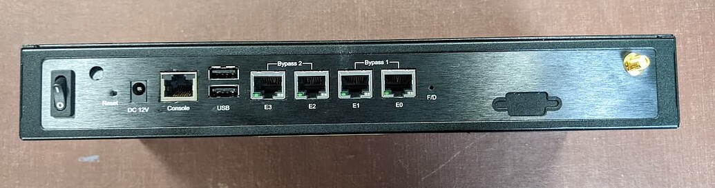
In terms of administrative access, it's pretty spartan; the only option is the RJ-45 console.

Under the hood, we have an Intel Atom D510 processor (invisible in the photo, since it is located on the bottom side of the main board), a stick or RAM (our test unit came with strangely generous 4 GB, so we wonder whether this was an upgrade done by the previous owner), a CF card slot (in the photo above, the CF card is removed), an Intel 82583V Ethernet controller, and an Intel 6230 Wi-Fi controller. Also present: a set of SATA ports (data and power) and internal space sufficient to install a SATA SSD or a 2.5-inch hard drive. There are four standoffs obviously intended for some sort of SATA device, but no mounting tray. Those adept at bending sheet metal should be able to fabricate such a tray (or an equivalent set of brackets) in a short order. In this HOWTO, however, we will stick to the CF card.
Power-wise, the device expects 12V / 3.33 A over a 5.5-mm barrel connector.
Note that the Wi-Fi card installed in the unit cannot work in access point mode, so we will not attempt to configure it here. In other words, we're going to set up a wired-only unit.
For this test, we will install OpenWrt on a 128 MB CF card, which will be just perfect for our needs.
There were two hardware accessories that we will need for this install, (1) a console cable (we used the kind that connects the RJ-45 console port to a USB port on the administrator's computer), and (2) a USB adapter for the CF card. Also needed: a computer running Linux.
Overcoming the Initial Weirdness
When you first get your hands on a CAD-0208, you notice that the four Ethernet ports are grouped into two pairs. Ports E0 and E1 are collectively marked Bypass 1, ports E2 and E3, as Bypass 2. This is because each pair can be set up to provide bypass connectivity. For our needs, this is not necessary, so we're going to make sure that bypasses do not interfere with our setup. To do that, we'll have to dive into the BIOS.
While the CAD-0208 is off, connect it to the administrator's computer with a console cable. Then, start a console connection at 19200 bits per second (bps). We did this with a command-line utility called screen:
sudo screen /dev/ttyUSB0 19200You can also use Putty or any other console utility, just set the correct connection speed.
Next, turn on the CAD-0208 and press the Tab key repeatedly until you get the main BIOS screen. Once there, press the right arrow key once; this will get you to the Advanced screen that will look like this:
  Main    Advanced    PCIPnP    Boot    Security    Chipset    Exit
********************************************************************************
* Advanced Settings                                   * Configure CPU.         *
* *************************************************** *                        *
* WARNING: Setting wrong values in below sections     *                        *
*          may cause system to malfunction.           *                        *
*                                                     *                        *
* * CPU Configuration                                 *                        *
* * IDE Configuration                                 *                        *
* * SuperIO Configuration                             *                        *
* * Hardware Health Configuration                     *                        *
* * ACPI Configuration                                *                        *
* * AHCI Configuration                                *                        *
* * ASF Configuration                                 *                        *
* * MPS Configuration                                 * *    Select Screen     *
* * PCI Express Configuration                         * **    Select Item      *
* * Smbios Configuration                              * Enter Go to Sub Screen *
* * Remote Access Configuration                       * F1    General Help     *
* * Trusted Computing                                 * F10   Save and Exit    *
* * USB Configuration                                 * ESC   Exit             *
* Bypass A Power On setting      [Normal]             *                        *
* Bypass B Power On setting      [Normal]             *                        *
********************************************************************************
            v02.61 (C)Copyright 1985-2006, American Megatrends, Inc.
Verify that both Bypass A Power On setting and Bypass B Power On setting in the bottom part of the screen are set to Normal. If not, use arrow keys and Enter to navigate to those fields and set them to Normal. Incidentally, if you've already noticed that in the BIOS, the bypasses are labeled A and B, while on the exterior of the device they are marked 1 and 2, congratulations! you're probably obsessive-compulsive. :)
If you had to change anything, use the right arrow key to get to the Exit screen, then select the Save and Exit option. (You could conceivably use F10 for that, but console connections often ignore function keys.)
At this point, you can turn the CAD-0208 off for a bit; we need to go get the software.
Getting the Software
Head to OpenWrt downloads site:
https://downloads.openwrt.org/
Find the Stable Release section and click on the version number (as of this writing, 22.03.2). Scroll toward the bottom of the page and click on x86. Then, click on 64. From there, download your installation image, either generic-squashfs-combined.img.gz or generic-ext4-combined.img.gz. Either image should work, and the installation routine will be identical.
Next, use your favorite image writing tool (dd, Etcher, what have you) to write the image you downloaded onto the CF card.
That's it for preparations. Time to install and configure OpenWrt.
Installation
Turn off the CAD-0208 and open the case. On CAD-0208, the top cover and the face place are combined into one piece. That piece is held in place by four Philips head screws, two on the bottom of the device near the front and one on each side, also near the front. Once you remove the four screws, the top/front cover easily slides forward, away from the device, exposing the main board. Install the CF card into its slot and close the cover. There's no need to put the screws back yet, but it makes sense to keep the cover on; it helps in cooling the processor (the unit has a small fan blowing air side to side, so putting the cover back on creates a tunnel for the air to flow through).
Connect the CAD-0208 to the administrator's computer with a console cable. Then, start a console connection at 115200 bps. We, again, did this with screen:
sudo screen /dev/ttyUSB0 38400And again, you can use Putty or any other console utility, just set the correct connection speed.
At first, you will see some garbage output (that would be the BIOS stuff that requires 19200 bps connection speed; you saw it before), but eventually, you should see the OpenWrt startup output. When you see the message asking you to press Enter to activate the console, do so. You will be shown the OpenWrt logo and taken to the command prompt.
Remember, right now, your CAD-0208 has no networking of any kind. To see if this is the case, you can run:
Now let's configure the device.
Configuration
First, you need to decide how you want to configure the CAD-0208. We wanted to bridge ports eth0, eth1, and eth2 info a single LAN and designate eth3 as a WAN port. To that end, we ran:
vi /etc/config/networkThis opened the network configuration file for editing. If you're familiar with vi, you can skip this paragraph. If not, vi takes a bit of getting used to. When you first start it, vi works read-only. To switch to the editing (or insert) mode, press i on the keyboard (i for insert). When you're done editing, press Esc; this will return you to the read-only mode. To exit, you need to be in the read-only mode. Type :x to save and exit or :q to exit without saving. This is the minimum vi skillset you will need.
Now back to regular programming... The first two sections of the network config file were config interface 'loopback' and config globals 'globals'; we left them unchanged, and then wrote the remainder of the file as follows:
config device
        option name 'br-lan'
        option type 'bridge'
        list ports 'eth0'
        list ports 'eth1'
        list ports 'eth2'

config interface 'lan'
        option device 'br-lan'
        option proto 'static'
        option ipaddr '192.168.1.1'
        option netmask '255.255.255.0'
        option ip6assign '60'

config interface 'wan'
        option ifname 'eth3'
        option proto 'dhcp'
It's almost self-explanatory. First, we define a bridge called br-lan and assign three physical ports to it. Then, we define a LAN interface, associate it with the newly defined bridge, and assign an IP address and netmask to it (elsewhere, a DHCP server for the LAN interface is already configured with sensible defaults, so we don't have to do anything here). Finally, we define a WAN interface, assign a physical port to it, and tell OpenWrt to ask for an IP address from an upstream device. If your upstream router expects a device with a fixed IP address, read up on option proto 'static' and option ipaddr.
When you're done editing, save and exit (Esc, then :x), To verify that the changes were saved, you can do:
cat /etc/config/networkTo apply the new network configuration, you can restart the networking to apply the new configuration:
/etc/init.d/network reloadbut Iwechose to reboot the whole thing instead:
rebootOnce you verified that everything works correctly, put the four screws back where they belong.
Housekeeping Tasks
At this point, there is one thing that you really should do and one thing that you may consider doing.
What you really should do is to set the root password, as right now, you have none. Type passwd in the command line and follow the prompts.
What you may consider doing is expanding the size of the root partition. When OpenWrt image is written on a disk, two partitions are created, and their sizes are fixed. As of this writing, the sizes of the two partitions are approximately 16 MB and 104 MB. This means that even on our tiny 128 MB CF card, we still have a few megabytes of usable space left, which we can absorb into the root partition. This might help if, for example, you plan to introduce additional packages to your setup some time down the road. If you decide to do this, we have a note for that, too... :)